
Thermoelectric Modules Handling, Packaging, & Ceramic Inspection Instructions
Handling
It is important that the thermoelectric coolers are handled correctly. Improper handling could decrease performance and possible premature failure.
- Never pull the leads up or to the side. If bending of the wire leads is required hold the heat shrink area which is close to the ceramic with fine nose plyers while supporting the module and bend at wire insulation only.
- Avoid excessive lateral shear force when handling thermoelectric coolers this may induce damage to the thermoelectric element.
- Sharp bend radiuses in the wire should be avoided and wires should be routed to avoid any sharp edges that could penetrate the wire insulation.
Packaging
When shipping and handling thermoelectric cooler products, it is important to use the correct container and methods. This has been tested to shipping standards and securely delivers material without breaking. Other packaging may not be suitable and cause material to break during transit, which makes it difficult for our Quality team to investigate.
- For single unit size with dimensions <35mm and 21 < W2 ≤ 32mm product, use foam P/N 467033-02, put 12 pcs per layer, 5 layers per box.
- For single unit size with dimensions <45mm and 32 < W2 < 40.5mm product, use foam P/N 467033-03, put 10 pcs per layer, put 5 layers per box.
Procedure
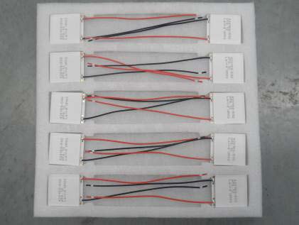
Place cold side of thermoelectric cooler face up to die-cut foam sheet with lead wires remaining straight. For long lead wire that requires folding, please use rubber-band to hold wires in place.

P/N: 467033-02
Put 12 pcs at most per layer
P/N: 467033-03
Put 10 pcs at most per layer

Put the foam and units into packing box, maximum 5 layers per box and put foam sheet on top layer. Close cardboard box, tape and ship. For multiple box returns please also include an outer packaging box for extra protection.

Inner Box

Outer Box
Ceramic Inspection
Reference datasheet and measure the length and width of thermoelectric cooler with calipers
- No copper trace or dice should exceed edge of ceramic.
- No more than 2 broken corners on each module is allowed.
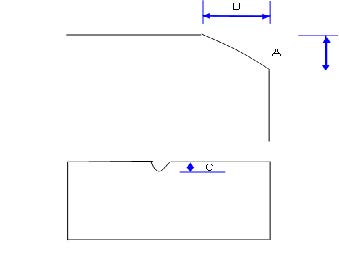
Using a microscope, visually inspect ceramic crack. No crack is allowed on the ceramic surface, but a ceramic chip may occur which will not affect performance of the thermoelectric cooler. It should be below this size specification:
- For ceramic > 30mm (length or width), A <1.0mm, B <1.0mm, C <0.5mm
- For ceramic ≤ 30mm (length or width), A <0.5mm, B <0.5mm, C <0.3mm
A pin hole or pitting may occur on the ceramic surface. If so the diameter needs to be ≤ 0.5mm. The bottom of the pit can be seen (visual inspection) and is acceptable. However, for more than two pin holes part should be rejected.
Inspect for any adhesive, solder, or general contamination. Residue that can be observed or felt by the finger on the ceramic surface should be rejected.
Inspect solder on side of ceramic using magnification. If no obvious solder remain it can be accepted.
There are no tin spots on the ceramic surface by visual inspection, the standard for black point and white point:
- The color is nearly between black, white point and ceramic surrounding, the diameter ≤ 1.0 mm and no more than three points on one side, which can be accepted.
- The variation of the color between black, white point and ceramic surrounding is obvious, the diameter ≤ 0.5 mm and no more than three points on one side, which can be accepted. (details refer to limited sample)


Illustrations of clean ceramic surfaces
